

-
Последние посетители 0 пользователей онлайн
- Ни одного зарегистрированного пользователя не просматривает данную страницу
-
Сообщения
-

Автор monahandrey1 · Опубликовано
Скетч использует 818 байт (13%) памяти устройства. Всего доступно 6012 байт. Глобальные переменные используют 9 байт динамической памяти. Это код из статьи...выходит 1кБ хватит на все -

Автор vmv7 · Опубликовано
Прежде чем советовать подобное, покажите фото сварных точек этим контролером. И тут же наперёд отвечу, точки там разные и пережаренные, потому-что нет синхронизации с фазой сети, поэтому длительность полуволны синусоиды там разная. -
Автор Владислав2 · Опубликовано
Нашёл фото своего прибора - купил на Авито за 500 руб. Обратите внимание на защиту. Был сожжён. Проверил, что голова целая. -
.thumb.png.3c9df22ca8a6c90aafa81a6eb9aabd50.png)
-

Автор korsaj · Опубликовано
А вы иногда просматривайте результаты нарушений техники безопасности и опыта наберётесь заочно. -
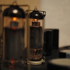
Автор Владислав2 · Опубликовано
Разберитесь, как рег. яркость ламп и убавьте. Иначе через пару лет выбросите. -

-
Рекомендуемые сообщения
Присоединяйтесь к обсуждению
Вы можете написать сейчас и зарегистрироваться позже. Если у вас есть аккаунт, авторизуйтесь, чтобы опубликовать от имени своего аккаунта.
Примечание: Ваш пост будет проверен модератором, прежде чем станет видимым.